
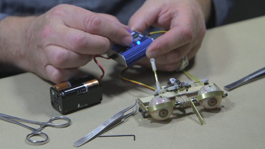
In this FREE excerpt from the Stan Winston School of Character Arts course, How to Build an Animatronic Head Part 2—Eye Mechanism Construction & Installation, VFX artist and master creature effects mechanic Craig Caton-Largent (Jurassic Park, Terminator 2: Judgment Day, Predator 2) shares effective, dare we say “eye-opening” techniques on how to attach and test eye mechanism servo motors. Plus, tips on using a servo tester without an RC transmitter or receiver!
Jump To Section
- Attaching an Animatronic Eyeball to the Eye Mechanism
- Using a Servo Tester and Cycler to Check Movement
- How to Center a Servo
- Adding the Animatronic Eyeball Vertical Servo
To watch the complete instructional video, click the player above!
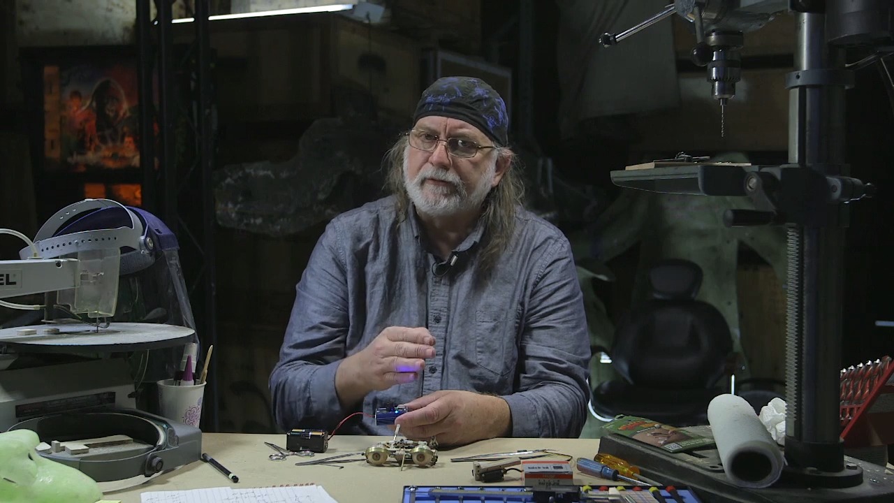
Whether human or robotic, it's often said that the eyes are the window to the soul. And servos are the magic behind making animatronic eyes move up and down and left to right, the building blocks of emotion and expression. In this lesson, Caton-Largent guides you step by step through the process of attaching and testing eye servos, ensuring they move with accuracy and precision. When it comes to the subtle effects that bring your animatronic character to life, the eyes have it!
Attaching an Animatronic Eyeball to the Eye Mechanism
To attach your animatronic eyeball to your eye mechanism, first insert the axle through the top of the eye and secure it with a dura-collar, aka a shaft collar.
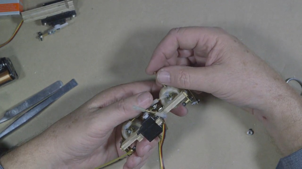 (Caton-Largent puts the axle through the top of the animatronic eye.)
The first dura-collar should be placed between the top of the eye and the piece of plywood that serves as the base for the mechanism.
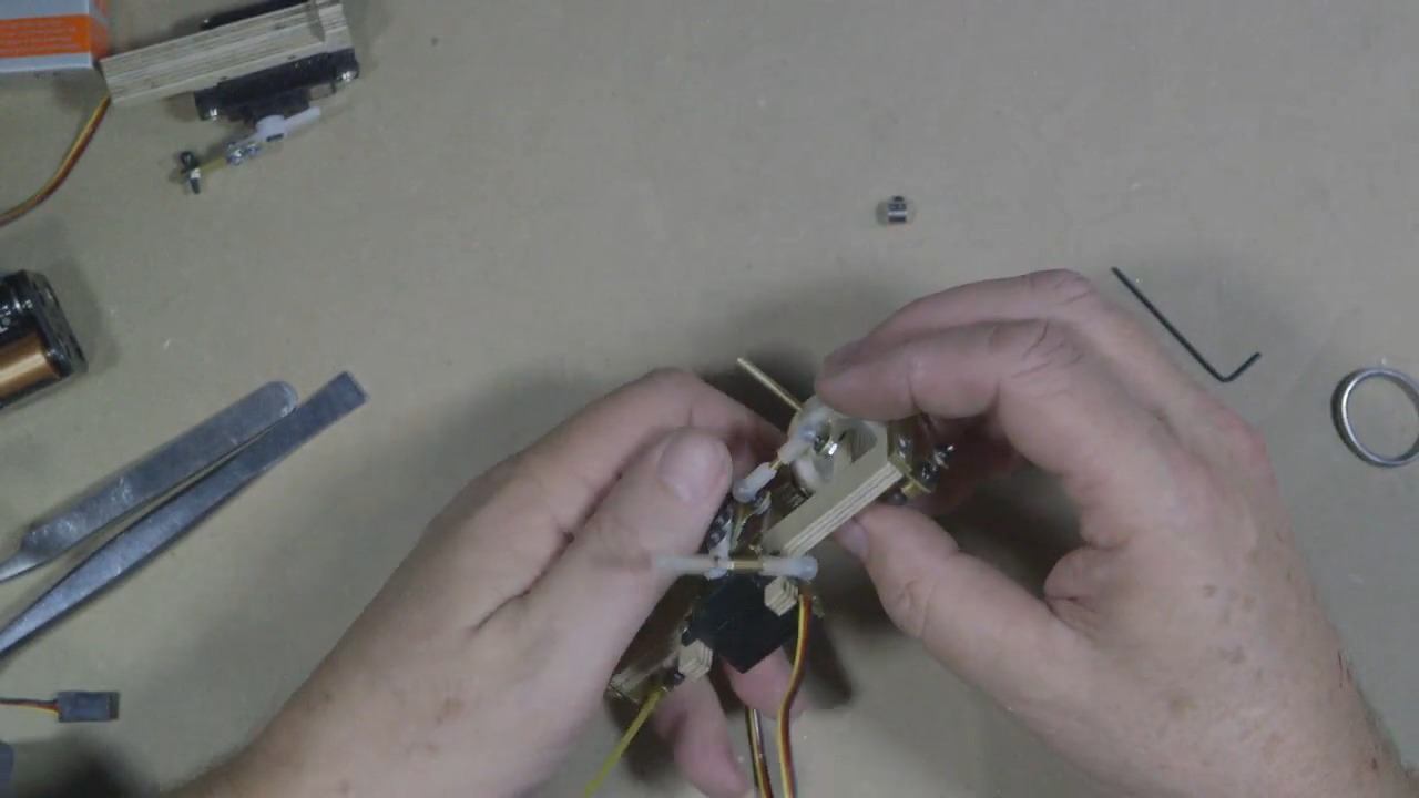 (Caton-Largent rotates his mechanism for a look at the axle before proceeding to the next step.)
Next, run the axle straight through the brass tubing placed inside the wood and screw the axle all the way down so it comes through the base of the opposite side.
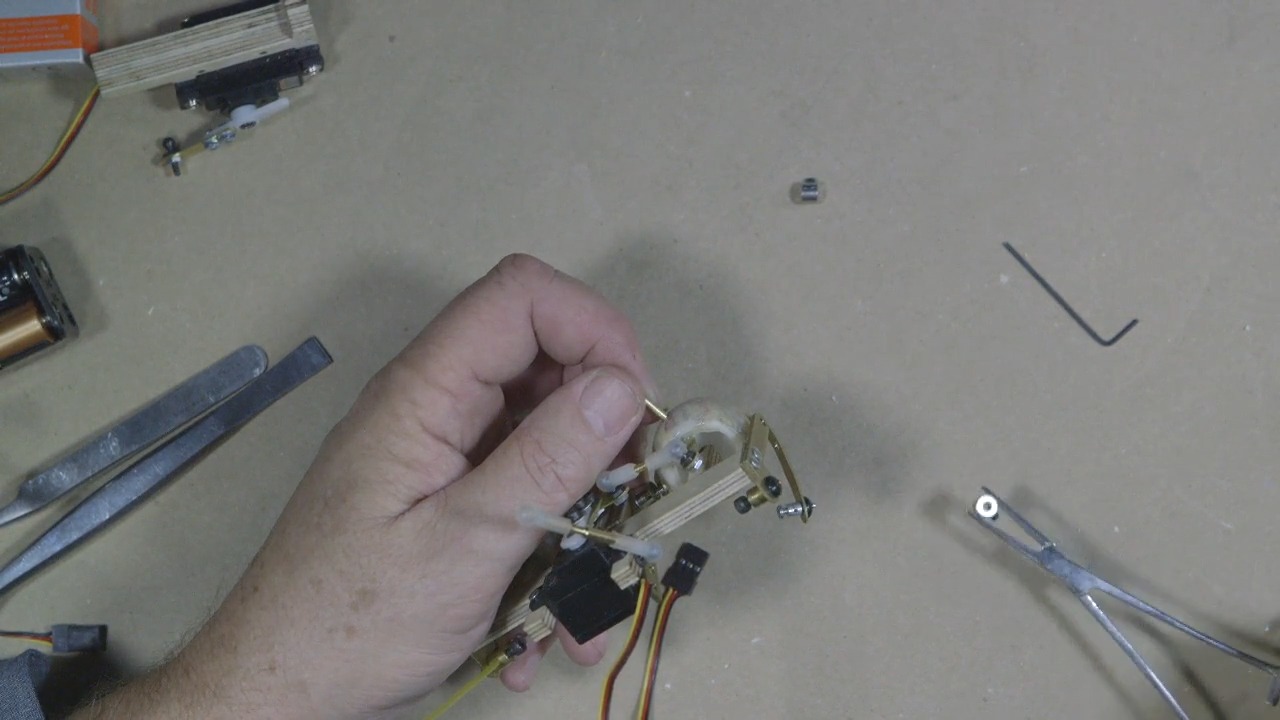 (Using fastening forceps, Caton-Largent picks up a dura-collar to place it between the top of the eye and the plywood base.)
Once through, you should be able to see the tip of the axle barely sticking out from the bottom of the plywood base.
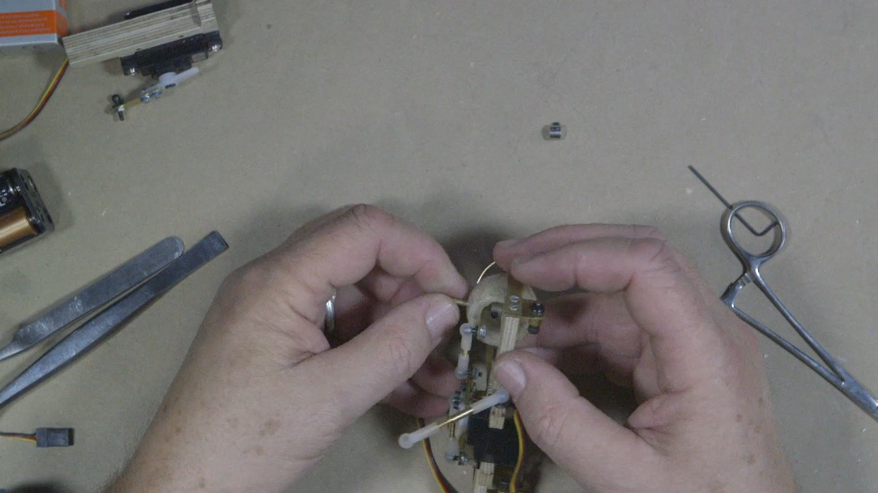 (Caton-Largent runs the axle through the brass tubing inside the wood base.)
Then, slip another dura-collar in between the end of the axle and the bottom of the eye.
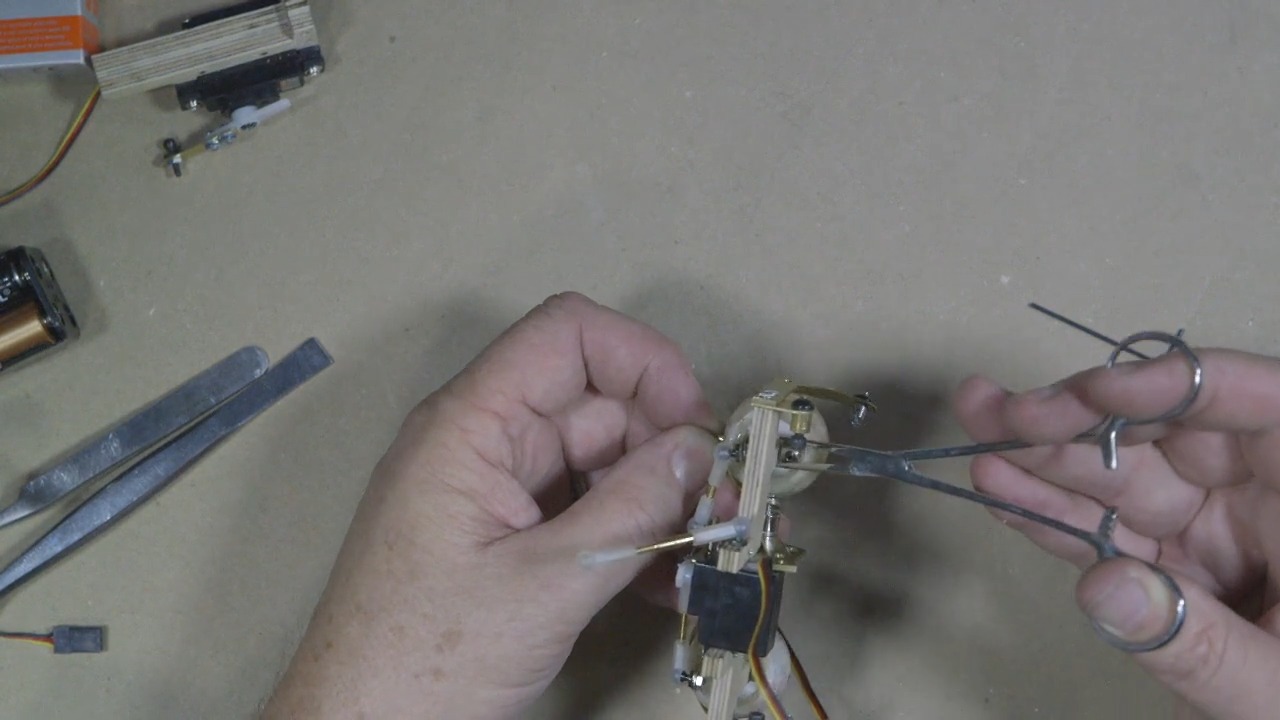 (Caton-Largent puts the second dura-collar in between the piece of plywood and the bottom of the eye.)
Run the shaft all the way down to the bottom and through the bottom of the eye. Hold the pieces in place so that both ends of the shaft are flush to the surface of the eyeball.
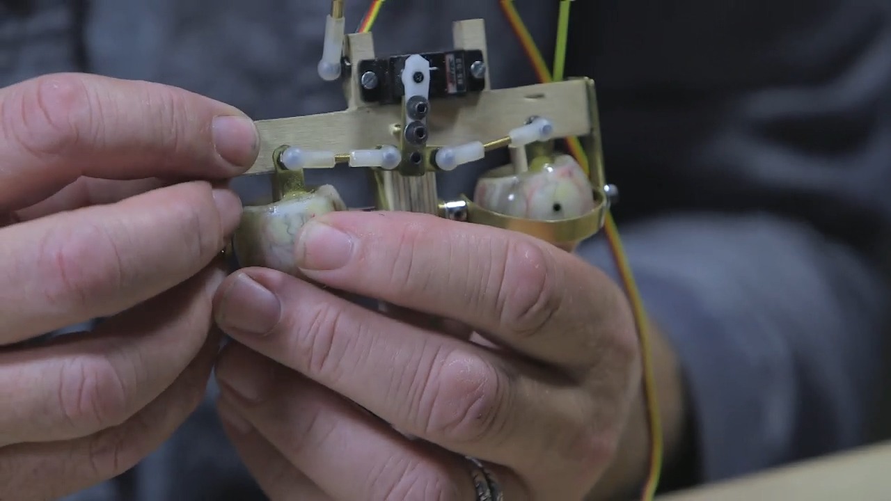 (Caton-Largent holds the shaft and the bottom of the eye together.)
Tighten the dura-collars to create a secure grip on the top and bottom.
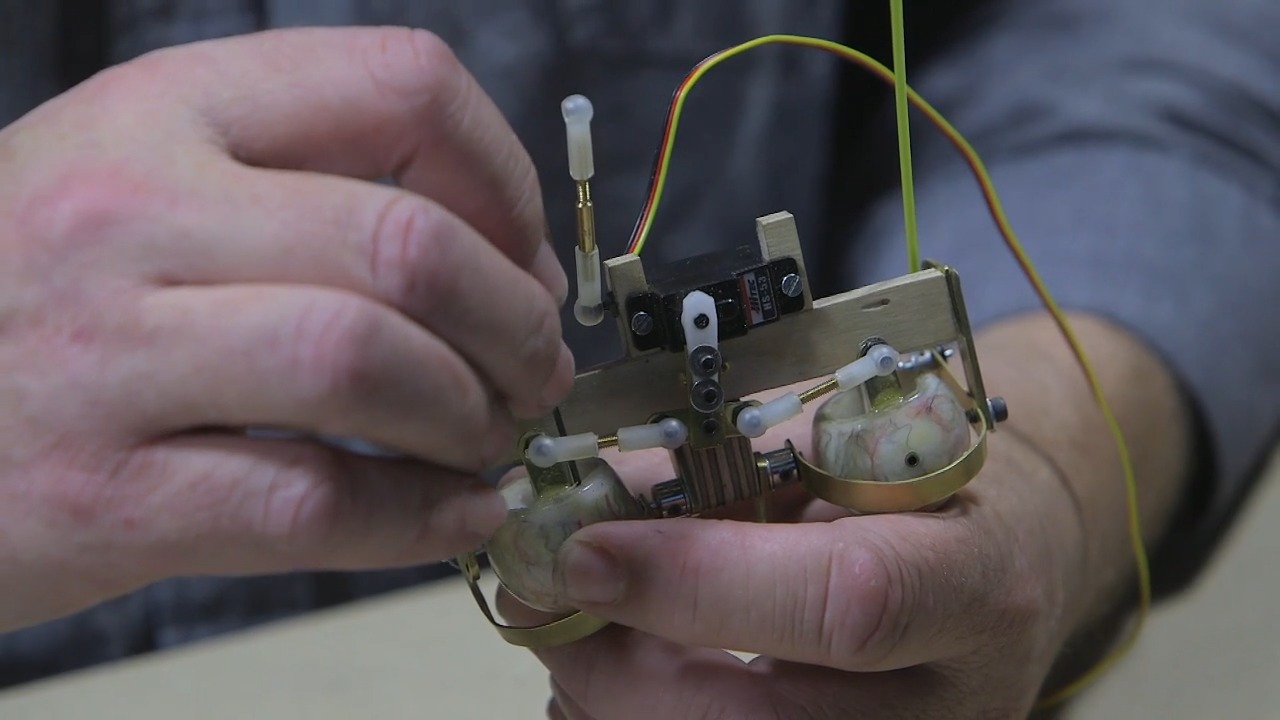 (Caton-Largent tightens the dura-collars.)
You’ll notice a bit of up-and-down slop, which is normal. This is because the shaft hasn’t been glued yet. However, a small drop of super glue will hold the pieces in place and remove any slop. If needed, you can go back into the dura-collars and adjust them.
Using a Servo Tester and Cycler to Check Movement
Now that you’ve put the mechanism on the eye horizontal, it's time to introduce the servo tester. This little device is a massive help, as it allows you to check if your servo is working as it should. It can also calibrate a center position.
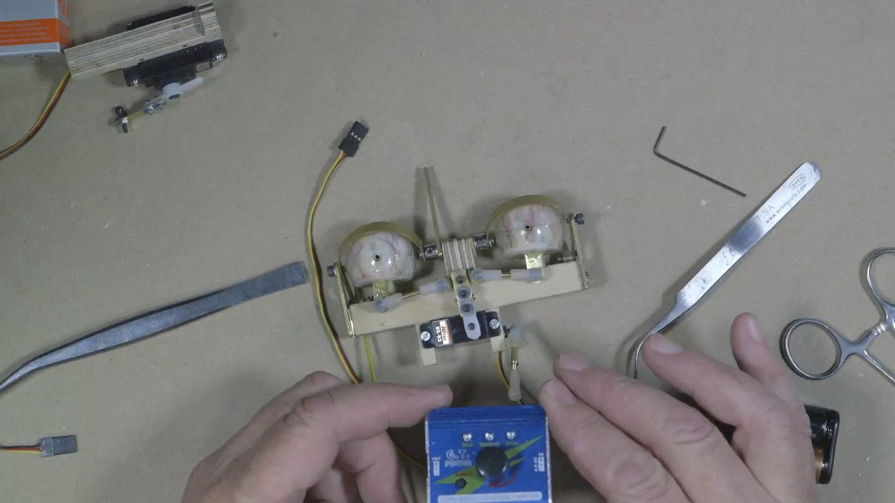 (Caton-Largent shows the servo tester/cycler he uses, the G.T. Power servo tester.)
There are many different types of motor servo testers available for use. One of Caton-Largent’s favorites is the G.T. Power servo tester, which features three modes for checking servos: manual, neutral, and automatic.
Simply, plug one side of the servo tester into a battery pack. Once you plug it in, you’ll see an “s,” indicating “signal,” and a positive and negative for the ground on your tester. On the servo wire, the yellow wire is the signal, the red is the positive, and the brown (or black, depending on the type of servo) is the negative.
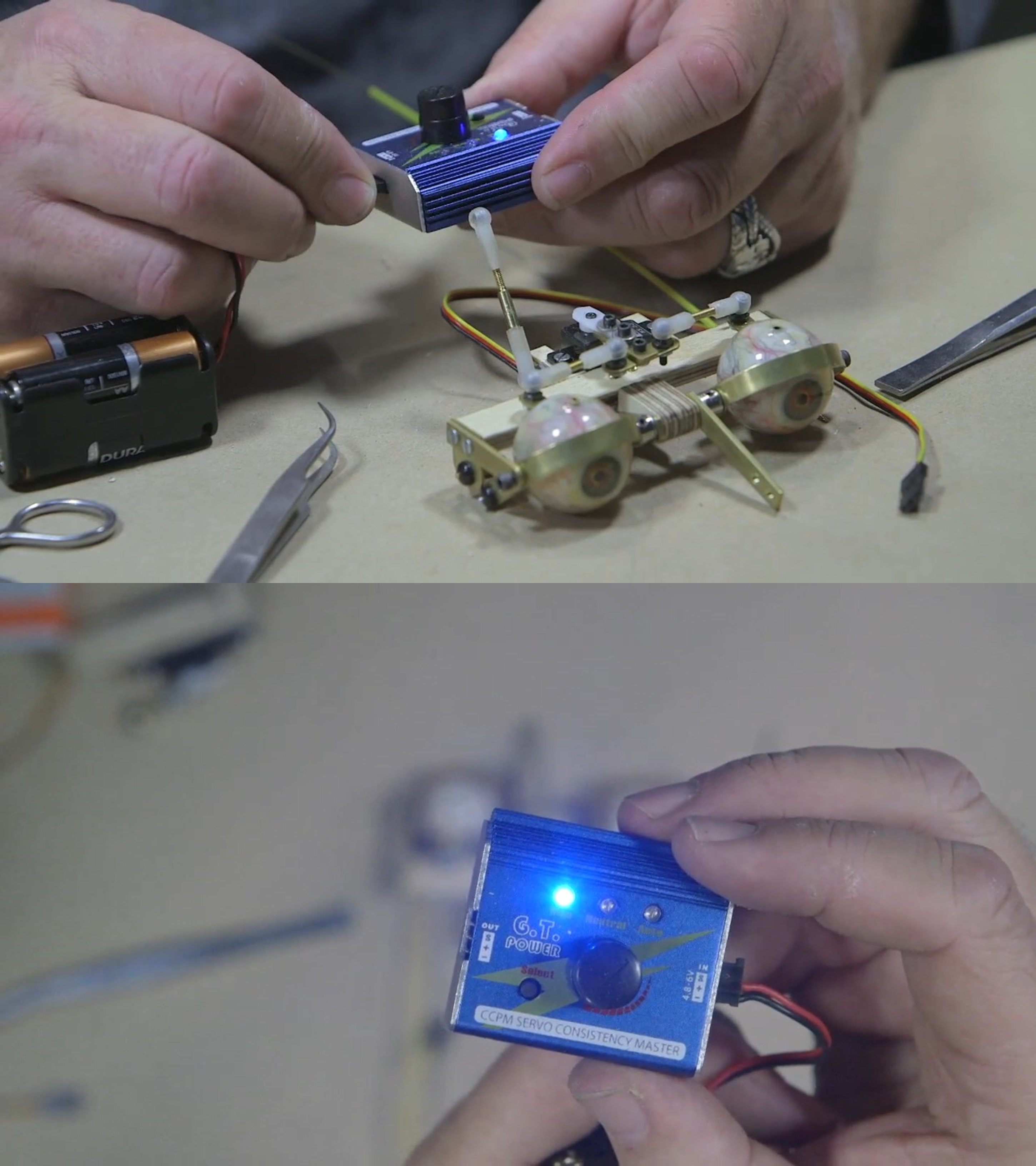 (Caton-Largent plugs the battery pack into the servo tester and shows how the tester responds.)
Next, plug one side of the servo tester into your servo.
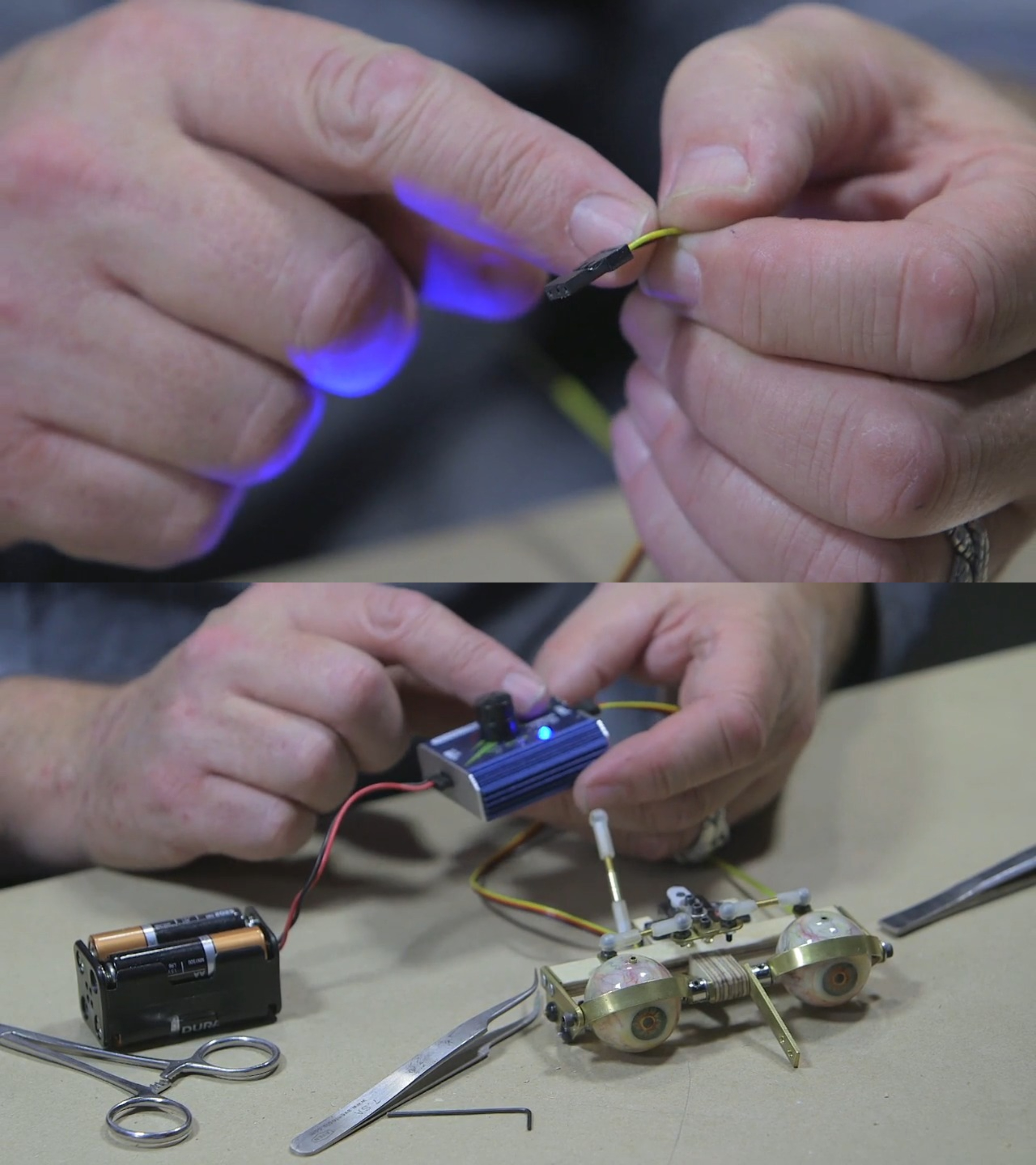 (Caton-Largent points out the different colored wires and plugs the servo wire into the tester.)
The manual setting enables you to move the servo back and forth, allowing you to check its range of motion.
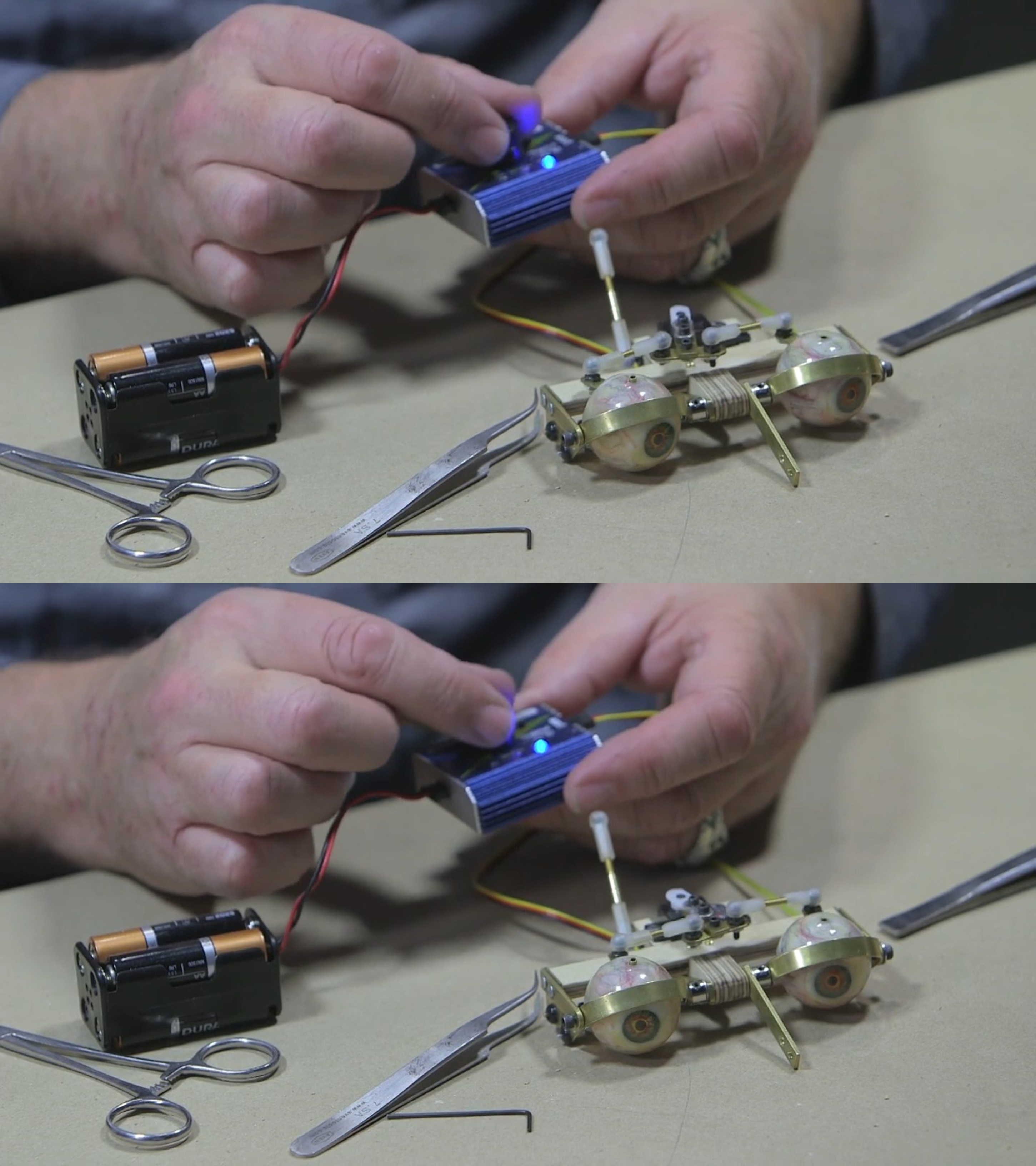 (Caton-Largent demonstrates what happens when you test the servos on the manual setting.)
The servo can go further than the throw of the eyes in this case. When the servo hits the limit of the mechanized piece it's moving, you’ll hear a light clicking sound. It is not advisable for the servo to be pushed beyond its limits, as this can cause damage to the internal disks and eventually render the servo inoperable. Using software, you can, like Caton-Largent, eventually, set the limit of the servos to the limits of the physical mechanism, avoiding wear and tear.
How to Center a Servo
The best reason to use a servo tester is that it centers the servo with a “center” setting. This comes in handy when assembling the servo on the servo horns, as you can put the tester on without needing a full radio control (RC) transmitter and receiver. Instead, you can pop the servo tester on and have an easy, efficient way to center it, ensuring the eyes are aligned and movements are calibrated.
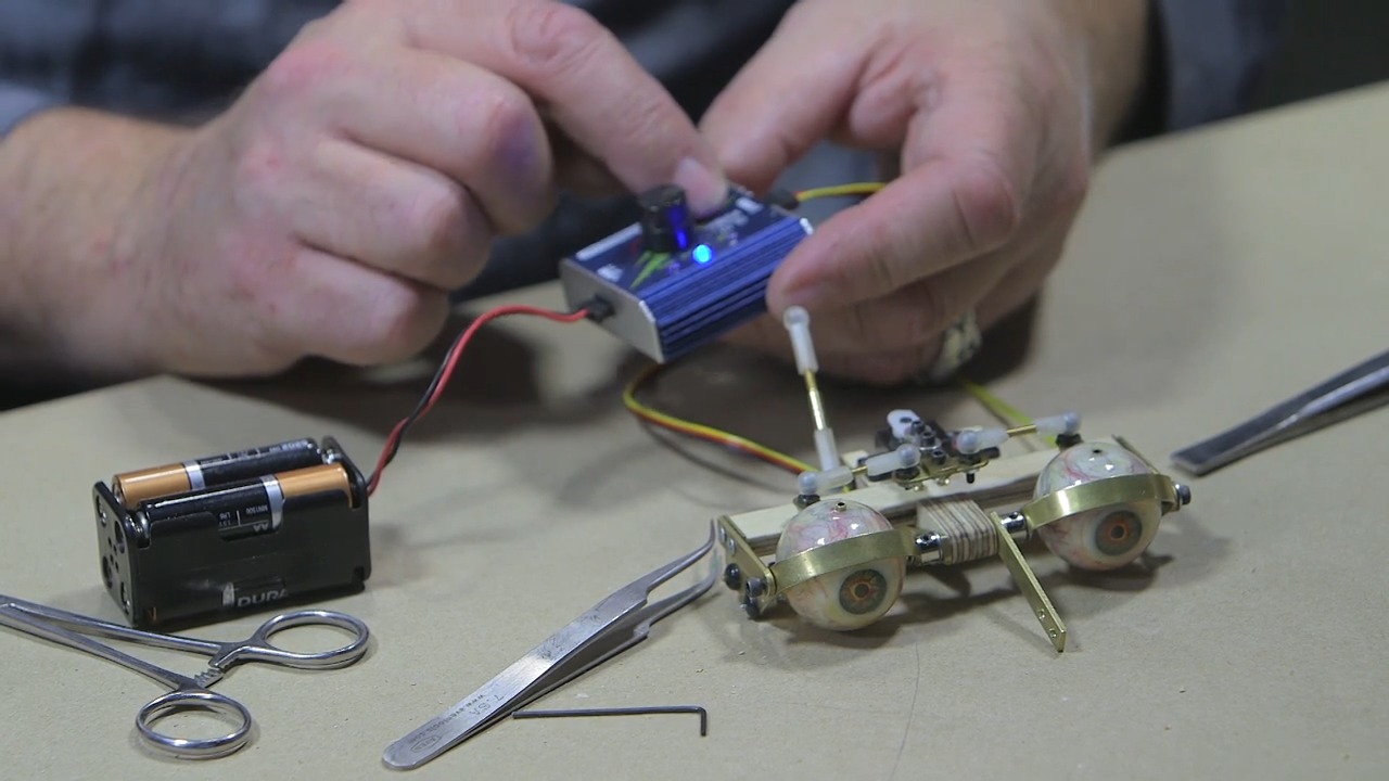 (Caton-Largent centers the eyes using a servo tester.)
The last setting is a “cycler.” This mode automatically cycles the servo through a range of motions to ensure smooth movement.
When manually turning your servo, it’s best to avoid making small and rapid movements, as this too can damage the small carbon discs inside. Carbon will get rubbed off of that servo, and all of a sudden, the servo is going to start twitching because it’s hunting for that little spot that it’s expecting to find on the carbon plate, but that carbon has been wiped off.
Once your servo is centered, you can unplug it and rest assured knowing that it’s properly calibrated to its centered position.
Adding the Animatronic Eyeball Vertical Servo
Now, you can attach the servo to the bottom of the servo mount, which is made from two pieces of plywood sandwiched together.
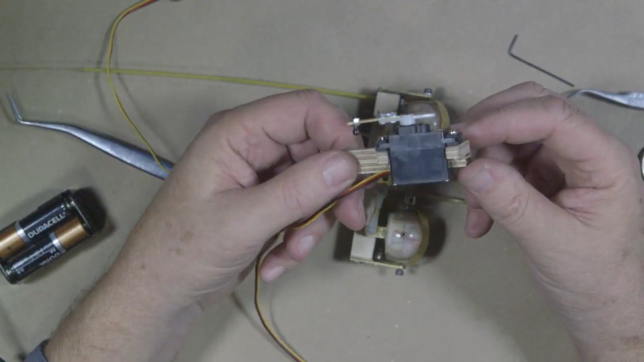 (Caton-Largent shows the mount he made using two pieces of plywood.)
One side has small arms on it, allowing it to hold the servo. The width of the base plywood matches the centerpiece of the upper eye mech base, so that the assembled pieces are more stable and less likely to wobble back and forth.
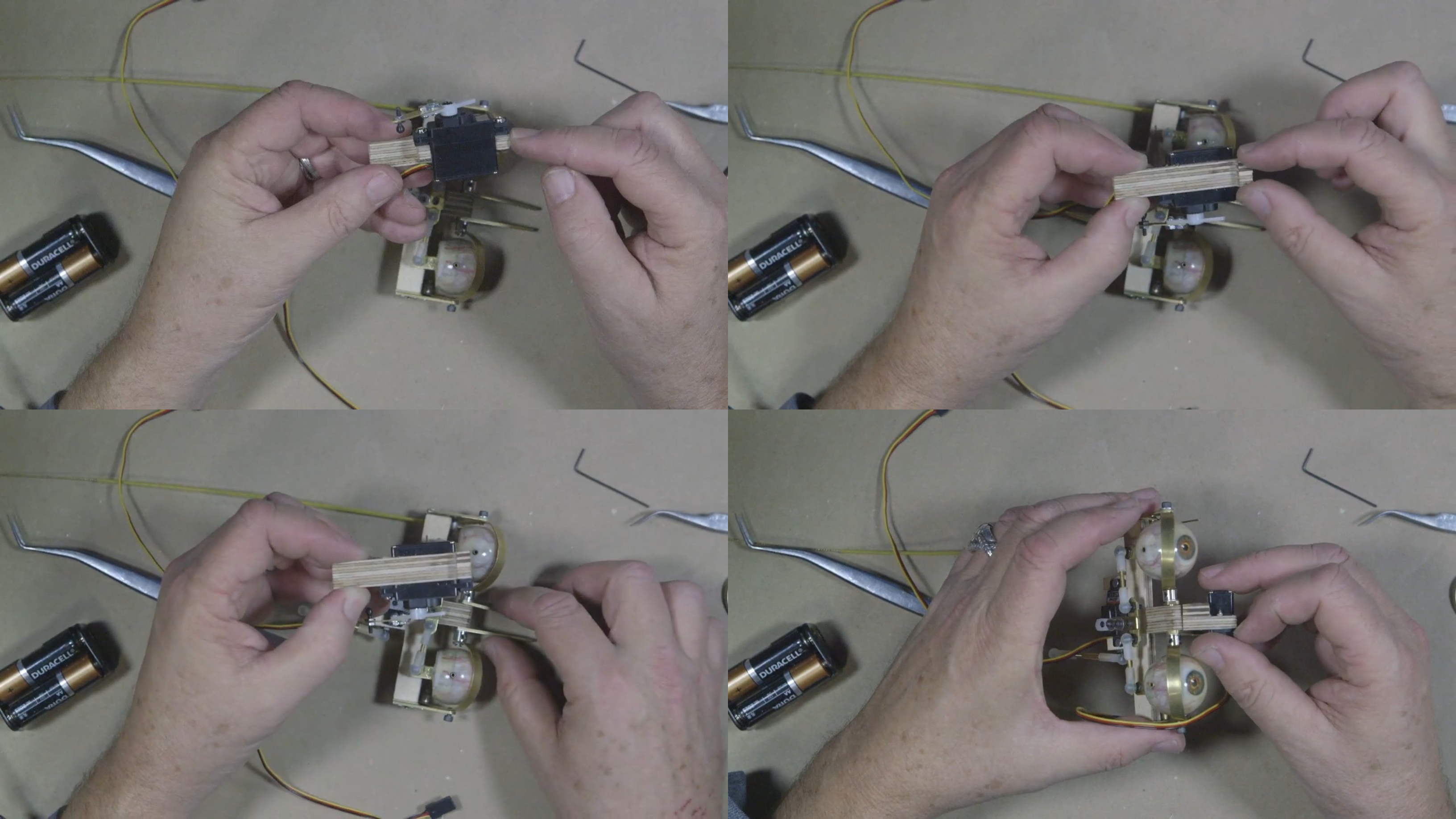 (Caton-Largent points out the thickness of his plywood mount and the thickness of the brass arms.)
To attach the servo to the bottom piece of plywood, you’ll use two 8-32 socket head cap screws with nuts on the other end.
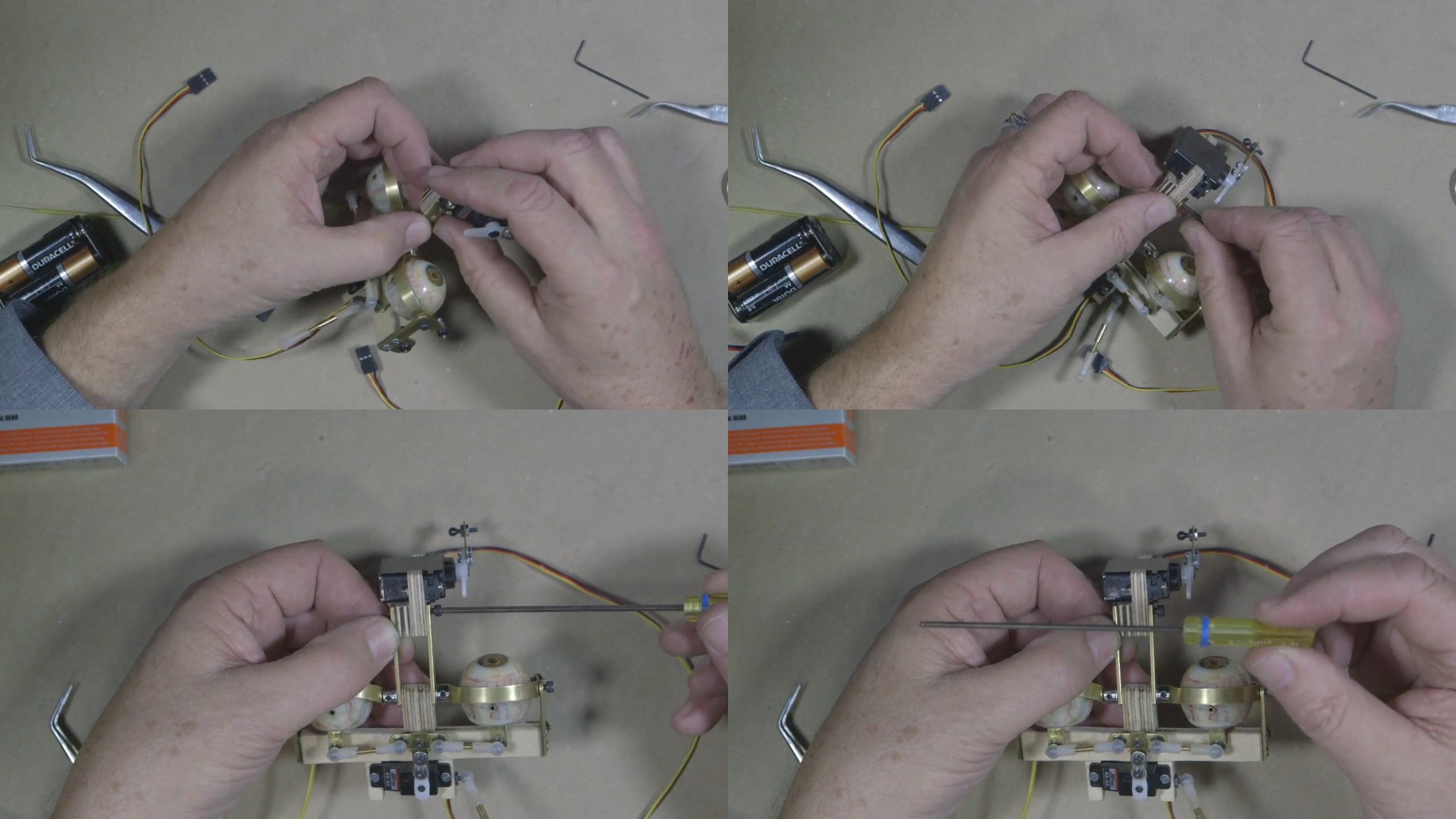 (Using 8-32 socket head cap screws and nuts, Caton-Largent attaches the plywood mount and two brass pieces.)
“When I was working at Stan Winston’s, we used a lot of 8-32 cap head screws, and what we did to identify our little screwdrivers was we put blue zip ties on them so we could go right away and quickly put something together so that nobody was waiting on us,” Caton-Largent says. “Because that was one of our things—nobody waits on us. It happened, but we tried not to let it.”
Next, attach the nut to the end of the screw.
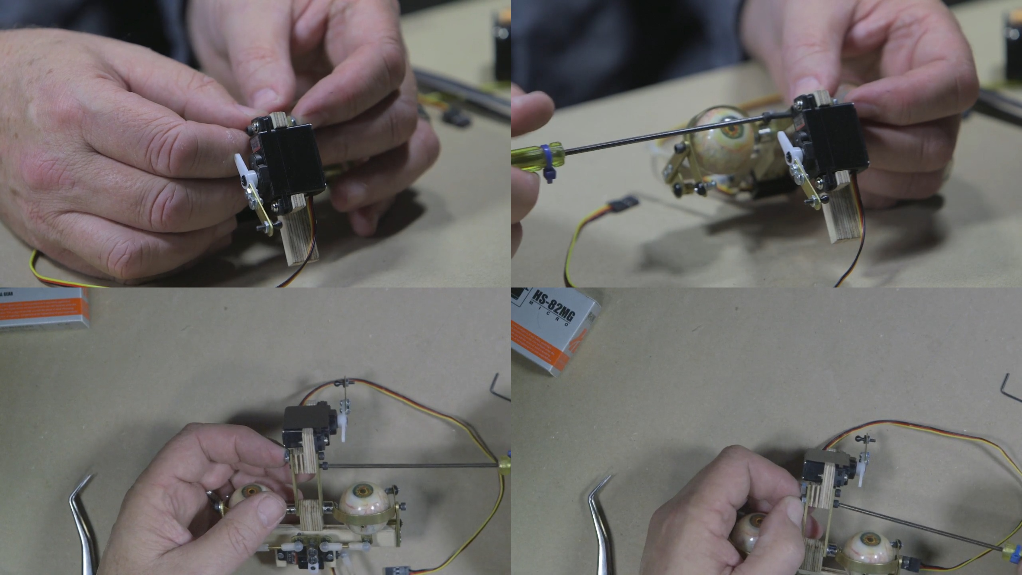 (Caton-Largent continues attaching the nuts to the screws.)
The two pieces of brass should sandwich onto the double piece of plywood.
Now that you’ve secured the screws and nuts, the lever mechanism is attached to the vertical. This will provide the vertical motion for the eye.
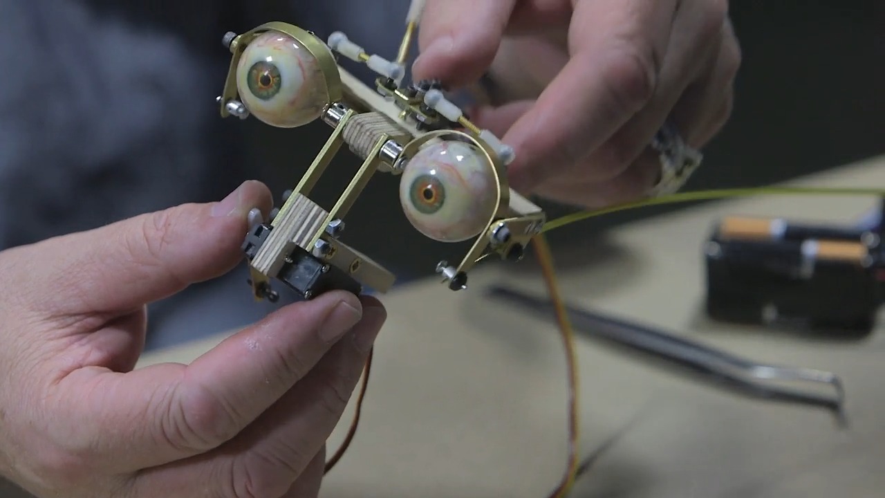 (Caton-Largent shows how all the nuts and screws have been attached to the verticals.)
Although Caton-Largent's demo piece features the servo at the bottom, you can alternatively place your servo on top. In this case, there isn’t enough room for the overhead.
On this vertical servo, you can add a small brass arm to give it a longer throw. Next, pop the DU-BRO socket head caps onto the rod bearings.
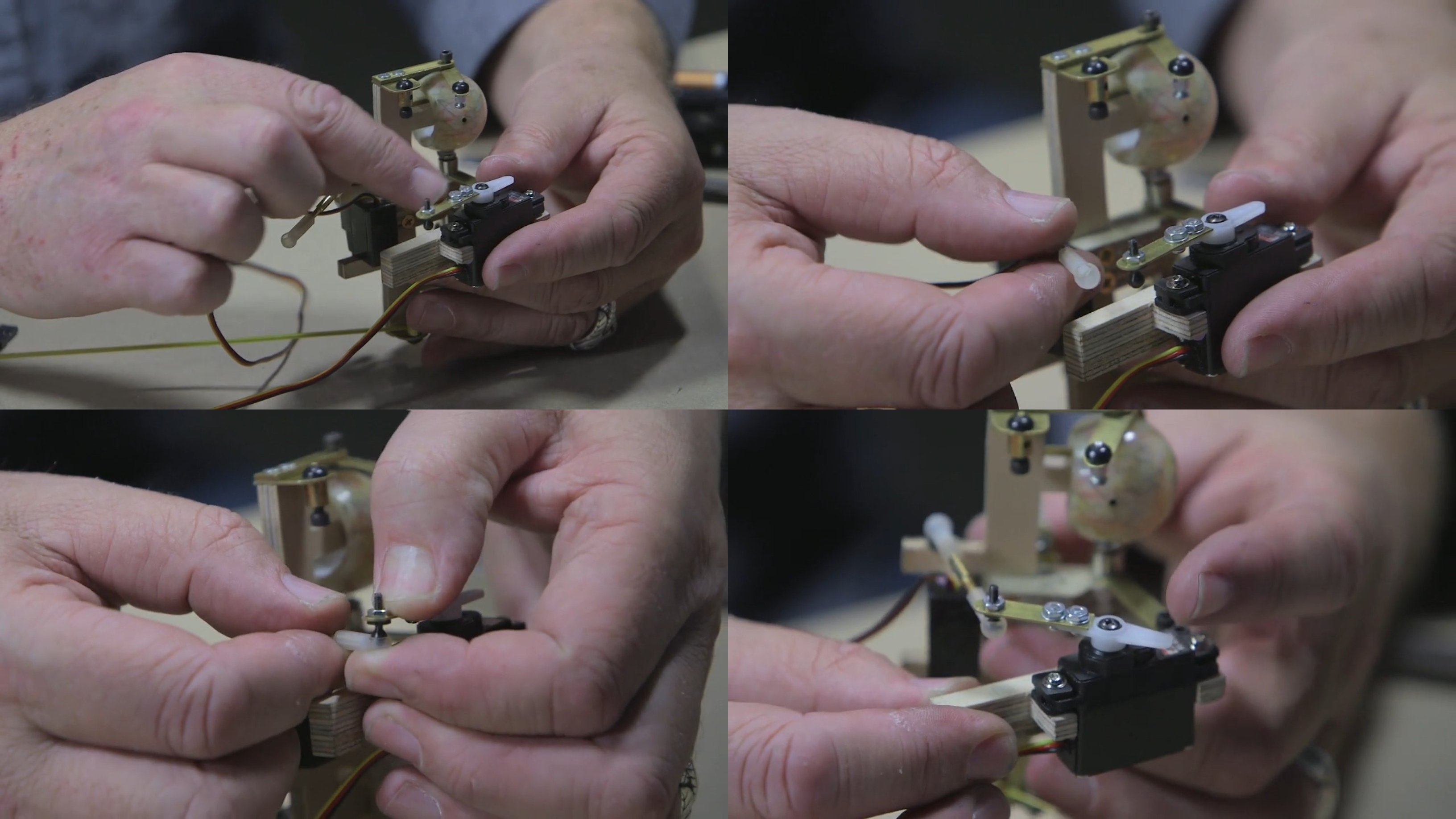 (Caton-Largent points out the small brass arm he added and the process of attaching the DU-BRO socket head caps to the rod bearings to make it functional.)
Now, watch the up/down servo in all its glory!
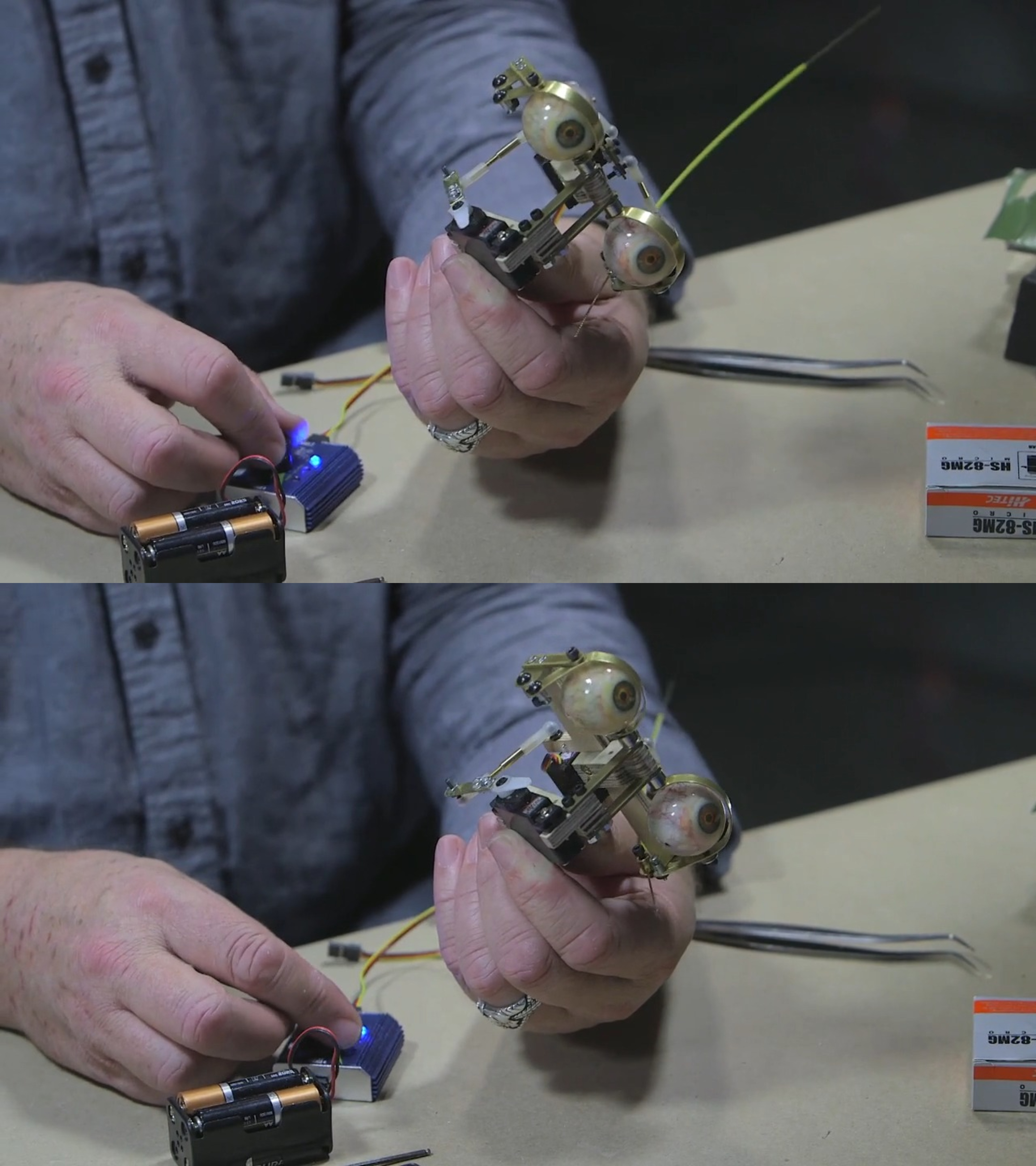 (Caton-Largent demonstrates how the up/down servo works.)
Test your servo with your servo cycler before proceeding to the next step. Hopefully, you'll find everything moving just as it should.
WATCH THE “HOW TO BUILD AN ANIMATRONIC HEAD” COURSE WITH CRAIG CATON-LARGENT:
How to Build an Animatronic Head Part 1 - Creating the Mechanical Underskull
How to Build an Animatronic Head Part 2 - Eye Mechanism Construction & Installation
How to Build an Animatronic Head Part 3 - Eyebrow & Jaw Mechanisms
How to Build an Animatronic Head Part 4 - Lip Mechanisms, Skin Testing & Programming